Note: This is an updated workflow for our original tutorial on receiving MIDI SMPTE Time Code (MTC).
MIDI Time Code (MTC) is a robust specification for sending SMPTE values from a master playback application—keeping the playhead of real-time visuals and music software perfectly in sync over a network or local MIDI bus.

In the past, displaying a live MTC readout in VDMX relied on a Quartz Composer patch to slice the incoming time values into standard Hours:Minutes:Seconds:Frames formatting. With Quartz Composer officially deprecated on modern macOS, we need a modern, native solution.
By utilizing a custom ISF shader, you can now process the incoming timecode directly on your GPU. Here is a step-by-step guide to generating an MTC signal, routing it into VDMX, and displaying a real-time SMPTE readout using ISF.
Step 1: Generate your MTC Signal
While you can use industry staples like Ableton, QLab, or Logic Pro to generate your master timecode, for this tutorial we will be using a free, lightweight application called TimecodeClock from Millumin.
Download and open TimecodeClock.
Set it to generate an MTC stream and route its output to an available MIDI destination on your Mac (such as the IAC Driver or a virtual MIDI port).
Hit play so the timecode starts rolling.

Step 2: Install the ISF MTC Display Shader
To replace the legacy QC patch, we've drafted an ISF generator that takes the raw seconds value from your MTC stream and mathematically reassembles it into a procedurally drawn 7-segment digital display.
Download the shader: VDMX MTC Display.fs
Move the downloaded
.fsfile into your system's ISF folder:~/Library/Graphics/ISFLaunch (or restart) VDMX so the software scans the new file.
Step 3: Connect the Shader to the Clock
Now that VDMX is successfully decoding the timecode, we just need to pass that continuous number over to our new ISF generator.
Create a new Layer in your workspace.
In the Media Bin Right-Click Add Clips from Built in Sources > ISF Sources > Generator > VDMX MTC Display. or Layer Source, select ISF Sources > Generator > VDMX MTC Display.
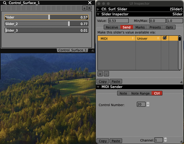
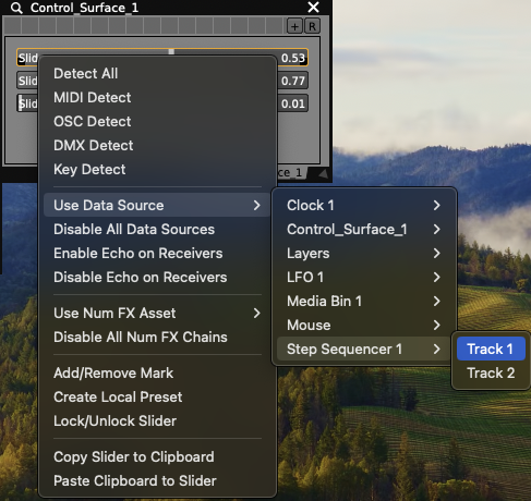
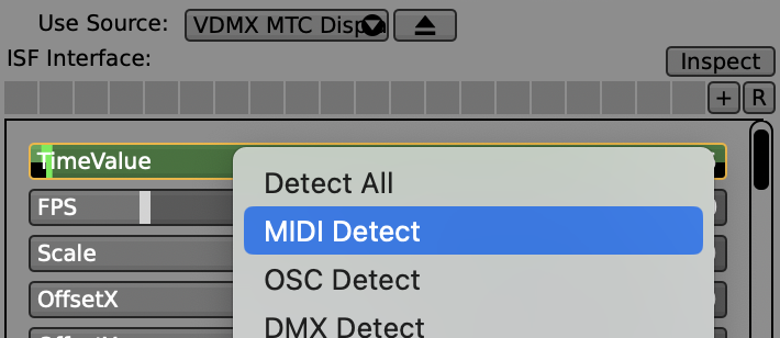
In the Layer Controls, locate the TimeValue slider.
Right-click the TimeValue slider, choose MIDI Detect. Assuming TimecodeClock is sending MTC, VDMX should detect the values coming in.
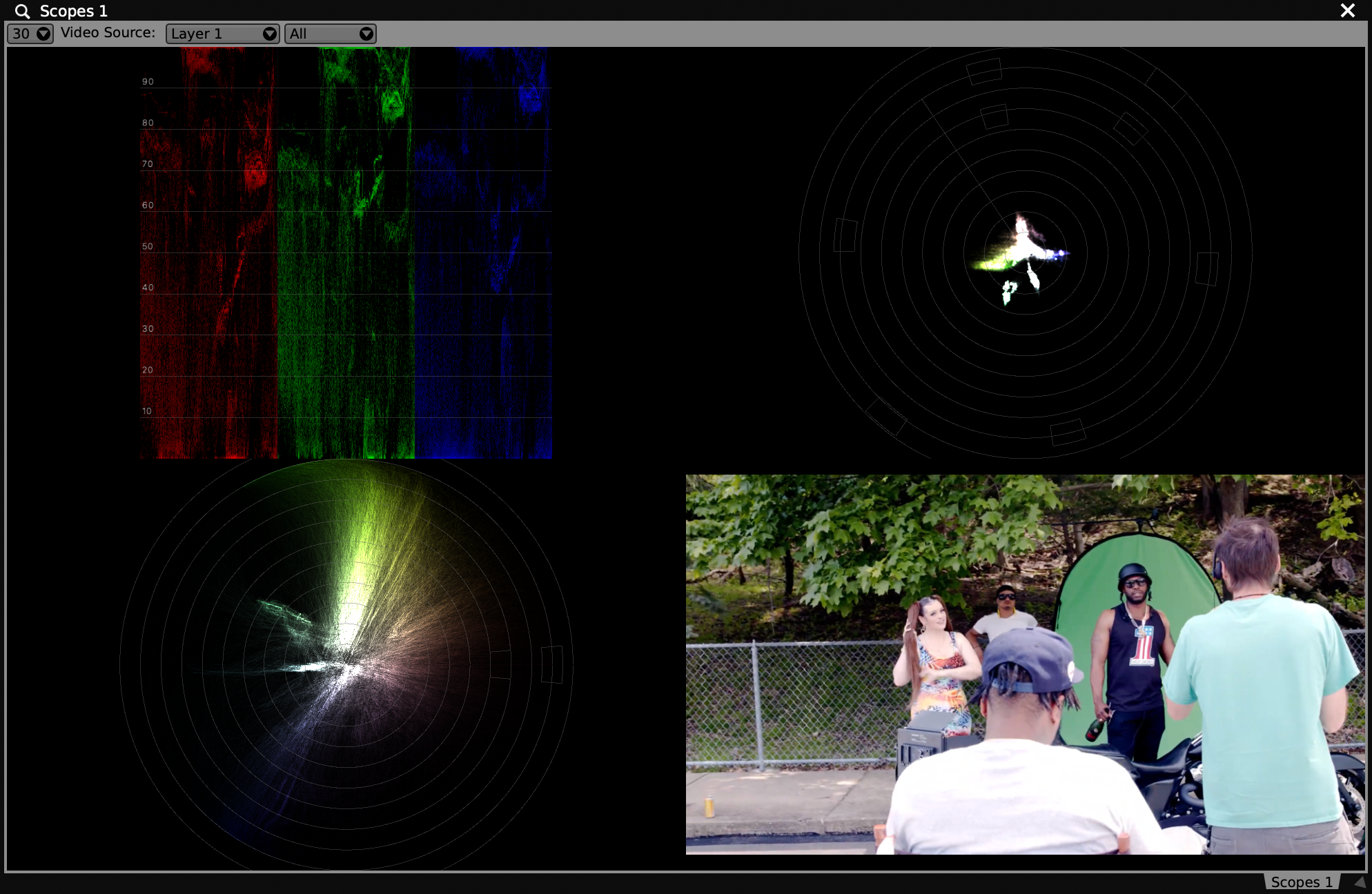
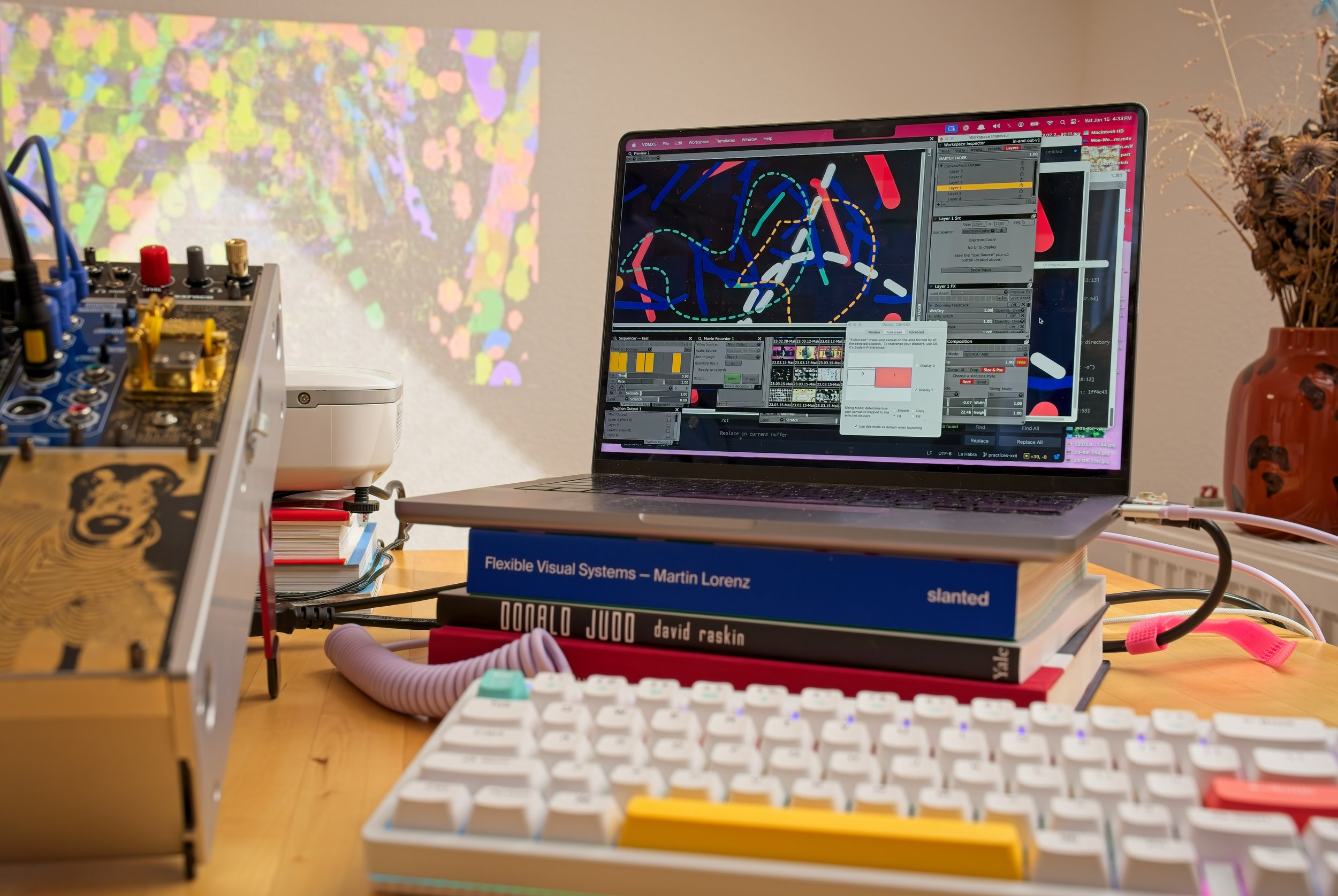
Troubleshooting: You can go to Workspace Inspector > Plugins > Click + to add a Comm Display.
Change the Type to MIDI and if you have routed the local MTC correctly through your IAC driver, VDMX should be detecting Quarter-Frame values.

Because the ISF shader renders a transparent background by default, your live MTC readout will seamlessly overlay on top of any video mix. You can use the shader's internal sliders to quickly adjust the scale, positioning, and thickness of the digital readout to fit your specific live production needs.